Login | Logout |

New Product Release!! JBR Hood Scoop Insert for GEN 2 Mazdaspeed 3

MS3-VENT-INSRT

Details:
Add aggressive styling and improve the performance of your Mazdaspeed 3 with the JBR Hood Scoop Vented Insert.

When used in combination with a front mounted intercooler, the JBR Hood Scoop Insert helps lower boost air temperatures faster by reducing negative under-hood pressure.

It doesn’t increase boost air temperatures when used in combination with a factory top mounted intercooler with factory ducting in place.

It keeps rocks, birds, bugs and other debris out of you engine bay and prevents damage to top mounted intercoolers.

It’s a simple bolt on application carefully designed to fit perfectly.

Available Finishes:

  • Mirror Red
  • Mirror Black
  • Mirror Blue
  • Mirror Clear
  • Unfinished

MS3-VENT-INSRT_11

MS3-VENT-INSRT_10


MS3-VENT-INSRT_09

Application:

  • 2010-2013 Mazdaspeed 3

Features:

  • Designed and Manufactured in the USA
  • Several finish options for endless color combinations
  • Quick and easy installation

Kit Includes:

  • 1 hood scoop vented insert Cover
  • Installation instructions are available online in our support section
  • Shipping is free in the US & our Hassle Free Lifetime Warranty is included

MS3-VENT-INSRT_03

MS3-VENT-INSRT_02

MS3-VENT-INSRT_04

MS3-VENT-INSRT_01


UTUBETwitter  Facebook 

New Product Release!! JBR Radiator Cover 2010 & Up Mazdaspeed 3

IMG_5646

Add some color and clean up that ugly space between the engine and front bumper of you Mazdaspeed 3 with a JBR Radiator Cover.

The JBR Radiator Cover for the 2010 to 2013 Mazdaspeed 3 was designed using the latest in coordinate plotting technology guaranteeing a perfect fit.

It’s been cut from thick and durable polyurethane sheet that will last a lifetime and never chip or fade.

Adding the JBR Radiator Cover completely covers the core support area leaving you with a classy finished look to your engine bay. Available in Red, Blue or black, it’s sure to compliment any color scheme.

IMG_5703

IMG_5710

Application: 2010-2013 Mazdaspeed 3

Features:

  • Designed and Manufactured in the USA
  • Thick durable polyurethane construction
  • Quick and easy installation

Radiator Cover Kit Includes:

  • 1 Radiator Cover
  • Installation instructions are available online in our support section
  • Shipping is free in the US & our Hassle Free Lifetime Warranty is included

UTUBETwitter  Facebook 

New Product Release!! Mazda 3 and Mazdaspeed 3 Oil Cooler Kits

Details:
Are you built and tuned? Are you a track Junkie? Are you both? Keeping the motor in your 2.3L DISI engine as cool as possible is going reduce knock and prolong engine life. Preventing the oil from exceeding normal operating temperatures will extend the life of your oil by reducing temperatures that prematurely break it down and increase engine wear. The OEM oil cooler uses a coolant based heat exchanger to keep the oil cool. Adding the JBR oil cooler will reduce the rise in coolant temperatures often seen when on track or during extreme temperature conditions.
 
The JBR Mazdspeed 3 Oil Cooler Kit employs a 19 row core constructed out of aluminum corrugated-fins & internal tubular plates greatly increasing both thermal efficiency and mechanical strength, so you get the smallest, lightest and more importantly, the most efficient oil cooler package.
 
Custom length commercial grade -10AN fittings and large ID stainless braided lines are the key to minimizing the pressure drop and making for an easy installation.
 
The polished billet aluminum sandwich plate incorporates an 1/8″ NPT port for additional gauges and sensors.
 
A custom mounting bracket and stainless steel hardware keep the core solidly mounted out front of the radiator maximizing its exposure to incoming airflow resulting in an oil temp reduction of over 28⁰F.
 
Applications
  • 2004-2013 Mazda 3
  • 2007-2013 Mazdaspeed 3*
 *Does not work with most conventional front mounted intercooler kits
 
Features:
  • Designed and Manufactured in the USA
  • Direct bolt on application
  • Corrugated-fin & tubular plate aluminum core
  • Commercial grade –AN10 fittings and large ID Stainless lines
  • +28⁰ drop in oil temps*
 
Includes:
  • 1 Oil cooler core
  • 2 Stainless braided hoses
  • 1 Sandwich plate & 2 1/8” NPT Plugs
  • 1 Application specific core mounting bracket
  • Stainless steel mounting hardware
  • 2 Aluminized fiber glass heat shield sleeves
  • Installation instructions are available in our support section
  • Shipping is free in the US & our Hassle Free Lifetime Warranty is included
 
*Ambient temperatures, track and road conditions, traffic and driving style can affect results.

 UTUBETwitter  Facebook 

Who’s tired of broken yellow zink sway bar brackets?

Who wants inexpensive high quality replacement bracket and bushing kits that will never rust or break and carry a lifetime warranty? Look no further!!
 
JBR now has our own line of replacement sway bar bushings and brackets for most all aftermarket front and rear sway bars. We also stock replacements for many OEM sway bars too!!
 
Did we mention these are warrantied for life and guaranteed never to rust or break??!!
 
If this wasn’t already pretty awesome, these are now the standard bushings and brackets included with EVERY JBR sway bar kit.
 
We know how tired everyone is having to replace broken sway bar brackets every year. NO MORE!!
 
Details:
No more cheap, rusted and broken yellow zinc coated sway bar brackets. JBR Sway Bar Bushings and Bracket kits are the toughest in the industry!
 
First, they’re laser cut out of .180″ thick stainless stainless steel which will never rust. This is nearly twice as thick as the typical bracket. They’re then die formed using our own propitiatory tooling that guarantees a perfect fit every time.
 
After forming, each bracket is then tapped to accept a grease fitting making maintenance simple and easy.
 
Included with every pair of JBR brackets are a set of 90a durometer bushings available in the most common OEM and aftermarket sizes.
 
Once you have these installed, you’ll never need to replace your sway bar brackets or bushings again.
 
Available Applications:
  • 2013+ Ford Focus ST OEM Rear
  • 2004-2009 Mazdaspeed 3 OEM Front & Rear
  • 2010-2013 Mazdaspeed 3 OEM Front
  • 2010-2013 Mazdaspeed 3 OEM Rear
  • 2004-2009 Mazda 3 OEM Front & Rear
  • 2010-2013 Mazda 3 OEM Front
  • 2010-2013 Mazda 3 OEM Rear
  • 2014+ Mazda 3 OEM Front
  • 2014+ Mazda 3 OEM Rear
  • 2006-2014 Mazda 5 OEM Front & Rear
  • 2013+ Mazda CX-5 OEM Front
  • 2013+ Mazda CX-5 OEM Rear
  • 2014+ Mazda 6 OEM Front
  • 2014+ Mazda 6 OEM Rear
  • 1.250″ (32mm) Aftermarket Rear Sway Bars
  • 1.125″ (28.5mm) Aftermarket Rear Sway Bars
 
Don’t see your application? Contact us, we probably have it.
 
Features:
  • Designed and manufactured in the USA
  • Stainless steel die formed construction
  • 90 durometer bushings
 
The JBR Tru-Torsion Sway Bar Bracket Kit Includes:
  • 2 Stainless sway bar brackets with grease fittings
  • 2 New 90 durometer polyurethane bushings
  • Lifetime warranty
 
UTUBETwitter  Facebook 

New Product Release!! Focus ST Oil Cooler Kits in Stock!

Details:
Are you tuned? Are you a track Junkie? Are you both? Within 10 minutes of being on track or an evening of repeatedly putting a few car lengths on your buddies STI, the oil temperature and coolant temperatures in your Focus ST can begin to rise in to unsafe territory which can eventually lead to overheating. Either of these conditions or a combination of both will result in prolonged excessive oil temperatures that prematurely breaks down the oil and increases engine wear.

The JBR Focus ST Oil Cooler Kit employs a 19 row core constructed out of aluminum corrugated-fins & internal tubular plates greatly increasing both thermal efficiency and mechanical strength, so you get the smallest, lightest and more importantly, the most efficient oil cooler package.

Custom length commercial grade -10AN fittings and large ID stainless braided lines are the key to minimizing the pressure drop and making for an easy installation.

The polished billet aluminum sandwich plate incorporates 2, 1/8” NPT ports for additional gauges and sensors.

Custom mounting brackets and stainless steel hardware keep the core solidly mounted out front of the radiator maximizing its exposure to incoming airflow resulting in an oil temp reduction of over 30⁰F.

Features:

  • Designed and Manufactured in the USA
  • Direct bolt on application
  • Corrugated-fin & tubular plate aluminum core
  • Commercial grade –AN10 fittings and large ID Stainless lines
  • +30⁰ drop in oil temps

Includes:

  • 1 Oil cooler core
  • 2 Stainless braided hoses
  • 1 Sandwich plate & 2 1/8” NPT Plugs
  • 2 Application specific core mounting brackets
  • 2 Aluminized fiber glass heat shield sleeves
  • Stainless steel mounting hardware
  • Installation instructions are available in our support section
  • Shipping is free in the US & our Hassle Free Lifetime Warranty is included

Follow us on social media for all the latest news, sneak peeks, and product releases.

UTUBETwitter  Facebook 

Suspension Part Three: The Pertinents

Going back to our last post (if you haven’t read Part Two yet, you should), we broke down the components of what makes up a coilover system, we’ve been over deciding that coilovers are really the best option and have discussed some of the key features of a set of coilovers. Now we need to dive deeper into some of the features that are icing on the cake. These are the bells and whistles found on premium suspension systems that make them worth that bit extra.

As you will recall, compression and rebound dampening are two major points of adjustment. Some coilovers offer only compression and other more  premium coilovers offer both. Why is this important? A vehicle in a track environment, or even on some twisty backroads, will receive four types of bias. Forward, rearward, left, and right bias are the four categories. When compression and rebound adjustments can be made, and those adjustments can be made on all for corners, then one can properly address all types of bias and conditions. This allows the user to tweak their suspension to perfection for any given condition and setup. Whether it be on the your daily driven street car, your dedicated track car or the more common daily driven track car, having control over your suspension is where it’s at.

Speaking of conditions, a primary concern of many is the ability to get great track performance out of a set of coilovers that is able to be driven with comfort on the street. Range of dampening is a key factor in this parameter. A set of coilovers labeled as “street” will typically have rather soft shocks. A set of coilovers labeled as “track” will conversely be rather stiff. Having a wide range of adjustability, being able to adjust both compression and rebound are what make a good set of coilovers great for both the street and the track!

Another very important feature found on a quality set of coilovers is camber adjustment. Often times the OEM suspension setup doesn’t allow for much if any camber adjustment. Camber or Camber angle is the angle between the verticle axis of the wheels and the vertical axis of the vehicle and can commonly be seen from the front or rear of the vehicle. If the top of the wheel is further “out” in relation to the bottom of the wheel, this is refereed to as positive camber. If the top of the wheel is “in” relative to the bottom, this is called negative camber. You will rarely see positive camber on a street car or road course car. You may see positive camber on an oval track car and it would only be found on the inside wheels. Negative camber is the more common setup due to the fact that it increases grip when cornering by increasing the tires contact patch. Having the ability to add additional negative camber over that obtainable with the OEM setup is a important feature of every driver that races their car. It’s even a requirement for those that just want to achieve a low ride height combined with the aggressive look of wider tires and need to get them tucked inside of the wheel well.

To adjust camber, coilovers employ what’s called camber plates to make these adjustments. You’ll primarily see them in the front simply because the front of most vehicles with the more common McPherson strut suspension do not have camber adjustment capability. This is not often the case with double wishbone suspension and coilovers for those vehicles typically do not come with camber plates.

Hmmm… I wonder if we can’t develop a set of coilovers that will be comfortable on the street, have both compression and rebound adjustability, camber adjustability where needed and perform the job duties on the track? Yes, Yes we can!

Now that the research is done and we know what we want out out a set of coilovers it’s time to build a few sets. With prototypes completed, the fun part is about to begin. The best part of being an aftermarket manufacturer is that testing needs to be done. We’re all car guys, so naturally taking the car to the track is not exactly a chore. It’s no secret that JBR is located in the greater St. Louis area. Aside from some AutoX action, there is not much venue for legal abuse to the extent that we’d like.

JBR’s testing process involved multiple levels. Typical spirited driving is in order for the entire JBR fleet and that happens frequently. What is the fun of owning a performance vehicle without driving it like it was designed? A step above is taken in the routine AutoX outing. Often times, when some early testing is needed on a new part, AutoX is a great tool. It is legal to get some abuse on the parts on this closed course, and gets some real world data based on how the parts will be used.

Although this is the routine light duty testing, the real stamp of approval needs to be received at the peak of conditions the parts will be subjected to. This is why frequent trips to various Midwestern tracks, such as Gingerman Raceway, Road America, Mid-Ohio and Pittsburgh International must be made to get proper testing done. High speeds and high cornering forces are coupled with extensive duty cycling at these venues.

Now what’s the beauty of owning a performance vehicle? We race the same cars that we get groceries with. Clearly being able to drive the car to the track, get the abuse in, and drive it back home would get the stamp of approval. This is where the beauty of the JBR prototype coilovers came into play. Not only did they perform extremely well on track, but off track as well. Due to the large range of compression and rebound adjustment incorporated into the dampers, the vehicle is able to achieve a cushy ride feel on the streets at the turn of a knob.

Follow us on social media for all the latest news, sneak peeks, and product releases.

UTUBETwitter  Facebook Email


Suspension Part Two: The Breakdown

Going back to our last post (if you haven’t read Part One yet, you should), we discussed some suspension basics. We know that two major components in a suspension that can be upgraded to optimize performance are springs and dampers. Springs can be thought of as a coarse control, with the dampers  being a fine control. When looking for the most performance and flexibility for different conditions, a full replacement is best. This is commonly known as a coilover system.

When looking at coilover options, an abundance of offerings will be found. Where does one begin to make choices? Spring-rate, dampening, compression, rebound, and independent adjustability of these are all items to consider when choosing a coilover system.

Spring-rate is a large factor in how a coilover will perform. Simply put, the spring-rate is defined as the amount the spring deflects over a certain load capacity. This rating can be made in either kg/mm or lbs/in. You will see kg/mm often shown as “K” and lbs/in often shown as “#” or “lb”. To understand and compare different systems to one another, use this chart:

700 lb/in = 12.5 kg/mm
650 lb/in = 11.6 kg/mm
600 lb/in = 10.7 kg/mm
550 lb/in = 9.8 kg/mm
500 lb/in = 8.9 kg/mm
450 lb/in = 8 kg/mm
400 lb/in = 7.1 kg/mm
350 lb/in = 6.2 kg/mm
300 lb/in = 5.3 kg/mm
250 lb/in = 4.5 kg/mm

So what does this mean? The stiffer the spring, the more load it will take to compress it. Essentially, body roll in cornering will become less when spring-rate is increased. Spring-rate is generally fixed rate on a set of coilovers. This coarse control by itself would result in a very “springy” ride. Rather than a tire staying planted on the tarmac, with a load applied, it would waiver between loaded and unloaded. An unloaded corner makes for loss of grip. This is where dampening comes in.

Compression dampening is the rate of reaction to a change in compression. This is the car pushing down onto the surface. The rate at which the piston compresses directly relates to the amount of compression dampening. This essentially aides the spring in absorbing fine changes in force exerted. This can be bumps in the road, slight turns, or say the car ends up on the rumble strips.

Rebound dampening does the opposite of compression, go figure. Rebound force comes into play when force is lessened on the road, say at the bottom of a dip in a pothole, in the bottom of a bump in the road, or on the exit of a turn.  More rebound will create more response on weight transfer out of a corner.

One can see how having a fixed spring-rate means that compression and rebound adjustability shifts the burden of your choice onto these variables. Most coilovers will be advertised based on how many clicks are on the dial. This refers to how many different settings there are for dampening. Although more options are better, this is not always the whole story. The range that these choices cover is really the thing to be looking at. Most users will be wanting to track their vehicle, but also have the flexibility to have a bearable ride on the street. A set of coilovers with tons of adjustments on one end of the spectrum does the user no good on the other end. This is why range is key.

Not only is range of concern, but compression and rebound do not always go hand it hand. To really dial a vehicle in for a specific setup and circumstance, these variables should be able to be controlled separate of one another. Though this feature is not something that is seen on the bulk of the coilovers on the market, it is available on quite a few and should be sought after if budget allows.

Ultimately, one must consider the use of the vehicle to make a decision. Often times, paying a little bit more money for a gain in versatility is a good choice. The better range of options offered, the more likely the coilovers will be able to accommodate for the various situations to be encountered.

Next in the series Suspension Part Three: The Pertinents

Follow us on social media for all the latest news, sneak peeks, and product releases.

UTUBETwitter  Facebook Email

Free JBR Phone, Tablet, AccessPort & Desktop Backgrounds

Here’s a perfect pairing to go with the parts you love. Show off your support for JBR with these free Phone, Tablet, Ford MFT and Desktop Backgrounds. From your computer, click on the image, then right click and save. From your phone or tablet, tap the image then hold down on the image and download.

Enjoy and Thanks for your support!!

Phone & Tablet Background

Desktop Background

Ford MFT

COBB AccessPort Background

Follow us on social media for all the latest news, sneak peeks, and product releases.

UTUBETwitter  Facebook Email

Suspension Part One: The Basics

Let’s start with the basics. Most seasoned car guys are aware of a choice between spring upgrades and coilover suspension systems. In the most basic sense, a spring refers to an elastic object with capability to store energy. For the sake of automotive suspension, the coil spring is referenced.

The rate of a spring directly relates to its deflection in a given load capacity. To get more specific to our automotive application, this coil spring is a compression spring. By definition, as load is increased, this spring becomes shorter. This is where roll occurs in cornering. OEM applications require a spring with a low spring rate to provide driving comfort and longevity of shocks/struts.

spring1

The OEM shocks and struts are hydraulic dampers. The job of a hydraulic damper is to control inconsistencies in form of oscillations of the spring. Lost yet? Think of it like the spring being a coarse control, while the damper is a fine control. The damper utilizes a piston with an orifice to transfer a gas or fluid through a piston chamber. The energy created from movement is converted to heat, which is dissipated through the gas or fluid. In an OEM application, this orifice is usually a fixed size. The size determines the rate at which the fluid transfers. The rate of fluid transfer relates to the rate at which the damper moves.

focusst

A spring upgrade is an inexpensive solution to accomplish a limited goal. Changing your coarse control value gives you an easy performance gain. By stiffening the spring and causing the OEM damper to sit at a more compressed average position cornering performance will be increased, but excessive load will be caused on the damper. Because of the fixed orifice, the damping and rebound rates are also fixed, which limits your fine control.

spring

Upgrading the suspension as a whole will net the best performance gains and long-term reliability. This is where options of a coilover suspension system come into play. The top level systems are designed with every control parameter in mind. Rather than limiting the setup with a fixed orifice, variable orifice valving is used. This allows adjustment. For the best control over your suspension, independent adjustable damping and rebound are desirable. This, in simple terms, means that user inputs allow both the up-stroke and the down-stroke of the piston in the damper to be controlled independent of one another.

In a street application, comfort is obviously going to be a concern. Though springrates are fixed in suspension systems via the compression spring earlier discussed, the damping and compression values are able to be changed. By setting these to softer settings, the dampers will absorb more road turbulence. This allows the cabin to be more level and comfortable.

In a track application, the only thing to be worried about is performance. Setting the damping and rebound to a stiffer setting will net the least roll in and allow for best cornering performance. This holds true until a stiffness is achieved in which rather than the body roll absorbing the sideways movement, the vehicle starts to slide. This is all dependent on road conditions, vehicle setup, etc. This is why adjustability is key.

Next in the series Suspension Part Two – The Breakdown

Like the information in this blog? Check out the James Barone Racing line of aftermarket performance parts!

UTUBETwitter  Facebook Email


There’s Nothing Positive About the 2.0L SkyActiv PCV System!

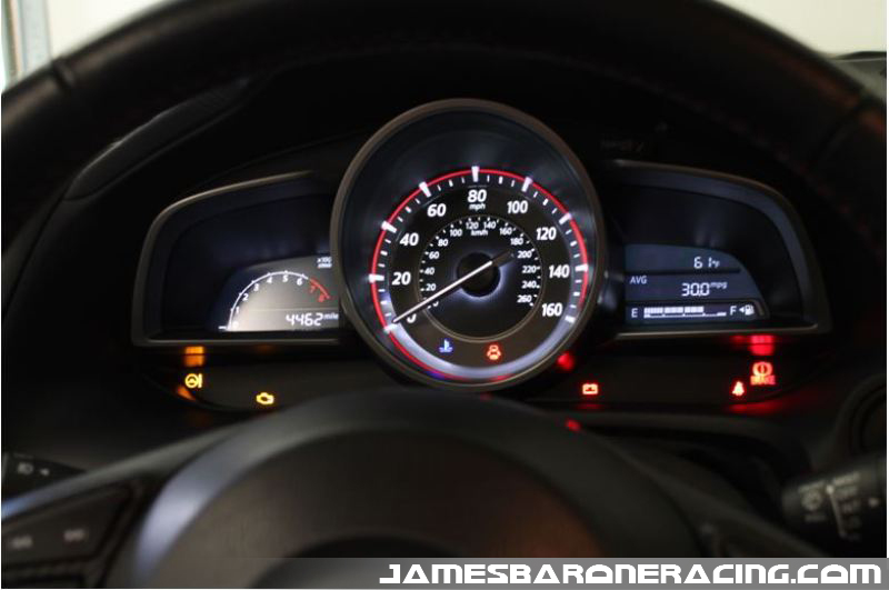
Recently, we had a customer bring their 2014 Mazda 3, 2.0L to us to install an oil catch can kit and to perform its very first oil change. With the car being so new, we asked if it would be OK to have a look inside at the current condition of the valves and document our findings. The car wasn’t to be picked up until the following day so we were given the go ahead.  With only 4462 miles on it, wait until you see what we found!

OK, so what is the PCV system and why is there a need for one? PCV stands for Positive Crankcase Ventilation. Simply put, the purpose of the PCV system is to ventilate the lower half of the motor that contains the motor’s crankshaft, connecting rods and balance shaft. When the motor is running under normal operating conditions, the oil becomes very hot. As the motors rotating assembly spins at very high RPM, a considerable amount of pressure is built up that must be relieved. For obvious reasons that we’ll go into more later, this can’t just be vented to the atmosphere. Instead, the hot vapor is released from the crankcase, routed into the intake manifold and burned as part of the combustion process. Sounds like a logical and efficient approach to the problem.  Unfortunately, the vapor released from the crankcase contains trace amounts of oil, fuel and water. Let’s take a closer look at what makes up the PCV system and the path it takes back to the combustion chamber.

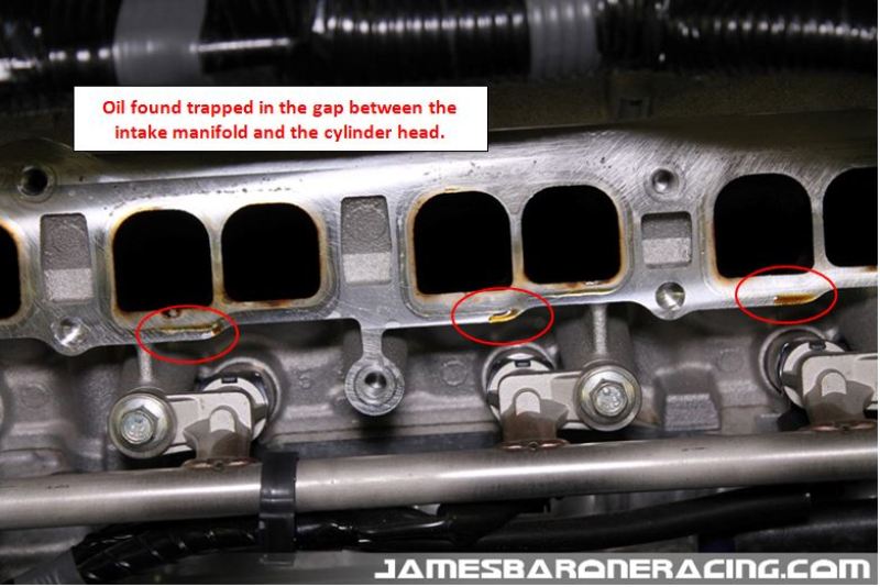
Let’s begin with the removal of the intake manifold. It’s pretty easy and took less than 25 minutes to get out of the car.

IMG_2911

Immediately, things began to start looking ugly. With the manifold removed we found the presence of oil on the head, in the gaps created by seals between the cylinder head and the intake manifold. Click on any of the pictures for a larger view.

2LMZOCC-2

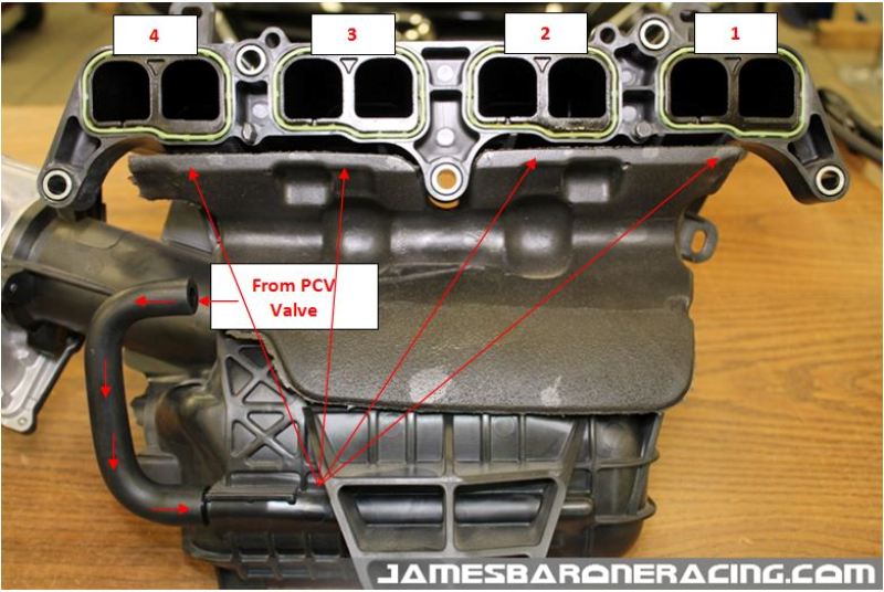
The next picture illustrates where the intake manifold mates with the cylinder head ports from the passenger side, port 1, towards the driver’s side, port 4. The seals that create the gap between the two are green and surround each intake runner. Take note of the proximity of the ports in relation to where the line leading from the PCV valve enters the intake manifold.

The next series of pictures will show the astonishing amount of carbon accumulation we discovered on the valves beginning with cylinder 1, the furthest from where the crankcase vapor enters the manifold.

2LMZOCC-3

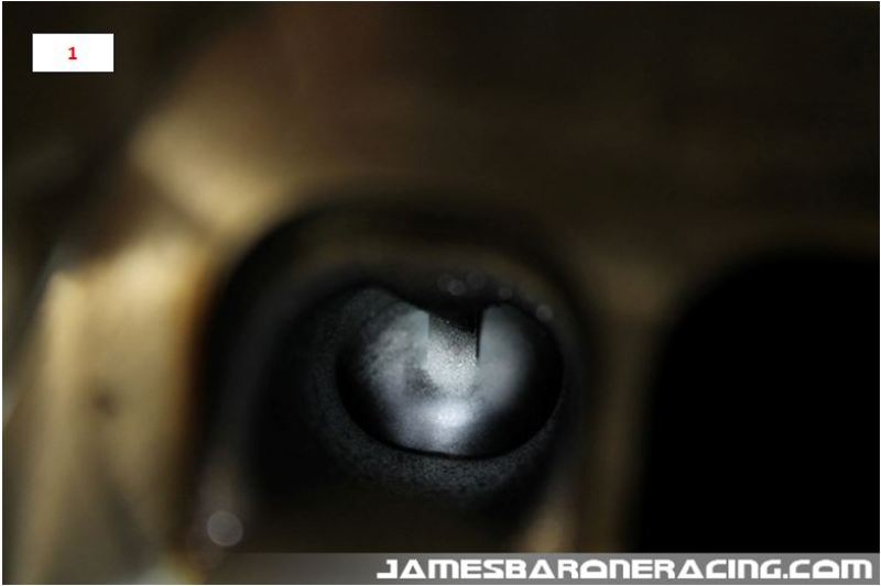
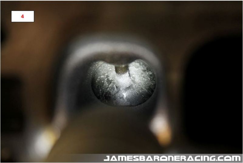
As you can see from the pictures above,  the valves for cylinder 1 are pretty clean and what we expected to see. As we moved to cylinders 2 thru 4 though, we can see significant accumulation, the worst being cylinder 4. The oil in the vapor is adhering to the back side of the hot valves and subsequently, it’s being baked on forming an impressive crust for such low mileage. The assumption for the increased build up from 1 to 4 is due to their proximity to where the crankcase vapor enters the intake manifold.

Why is this build up of crust bad? The valves are designed to seat in machined surfaces within the cylinder head. This creates the needed compression when it’s time for that particular cylinder to fire. When the build up of carbon becomes excessive, the valves are no longer able to seat properly, reducing power that robs your engine of performance and increases the amount of money you spend at the pump.

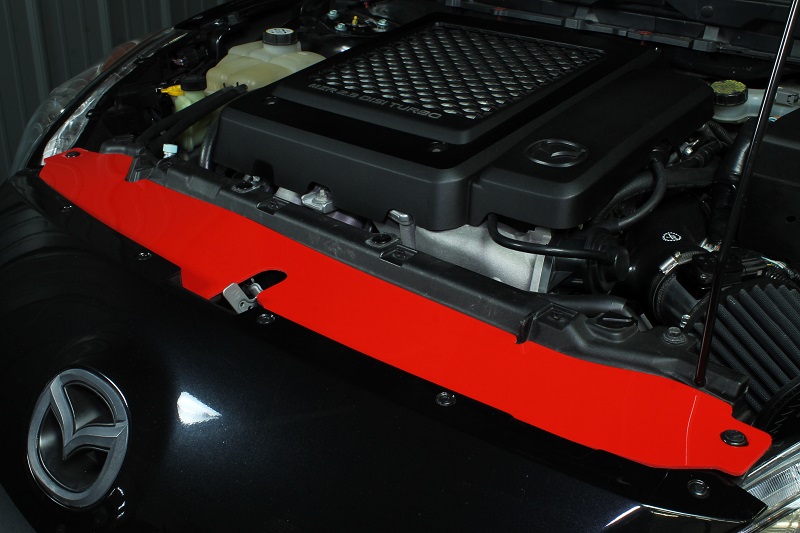
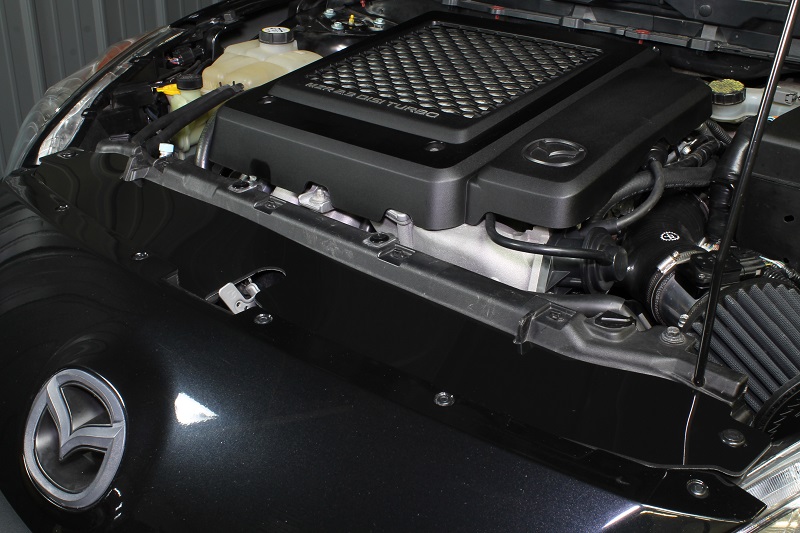
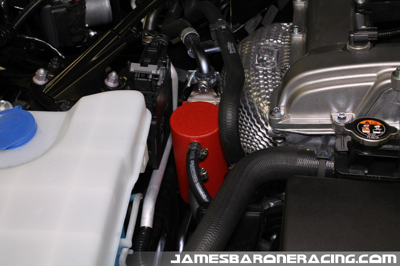
We reinstalled the intake manifold, changed the oil and installed our oil catch can kit. When the customer came to pick up the car we explained what we found, reviewed the pictures and agreed, this motor will certainly benefit from an oil catch can.

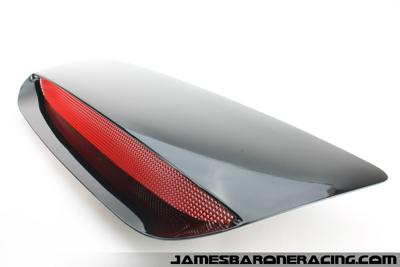
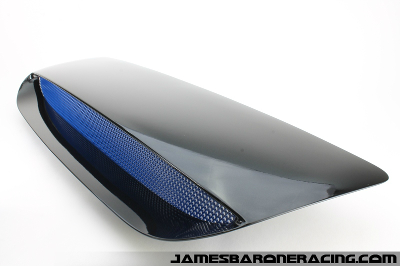
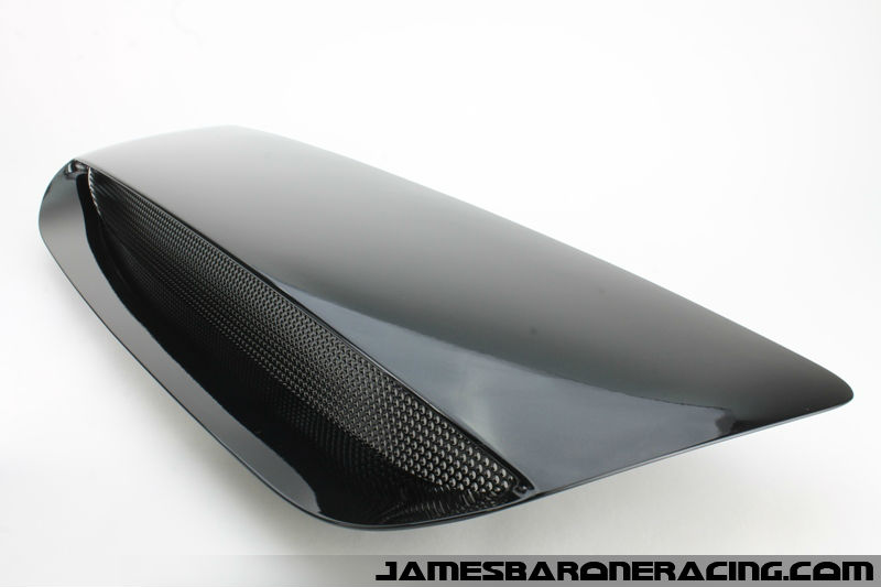
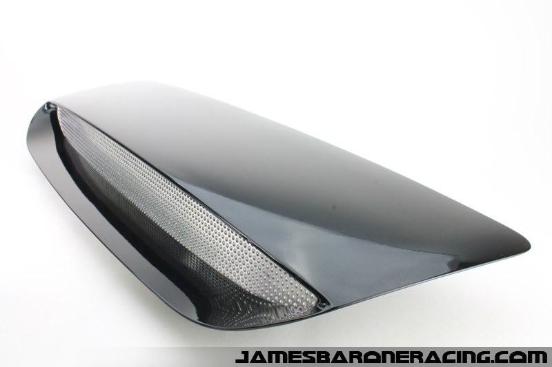
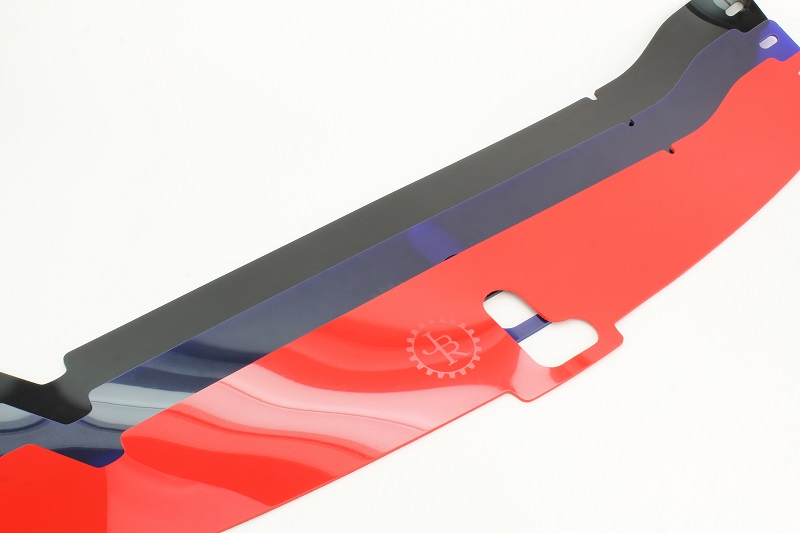
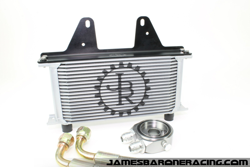
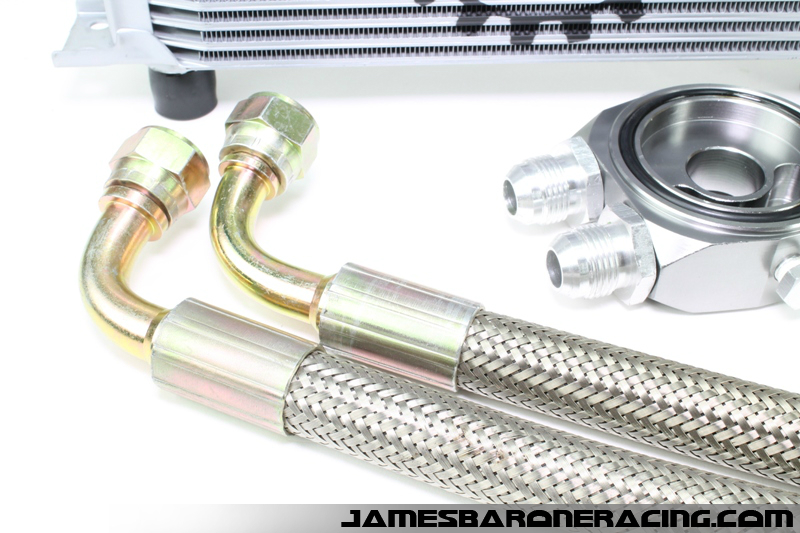
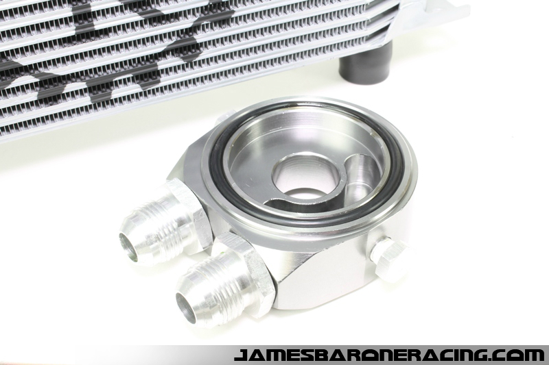
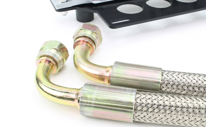
So that brings up the next question, what is an oil catch can and how does it work? An oil catch can is a can that contains some form of baffling that captures the oil present in the vapor released from the crankcase. The can is plumbed in-line between the crankcase and the intake manifold. Let’s take a deeper look into the catch can and the PCV system.

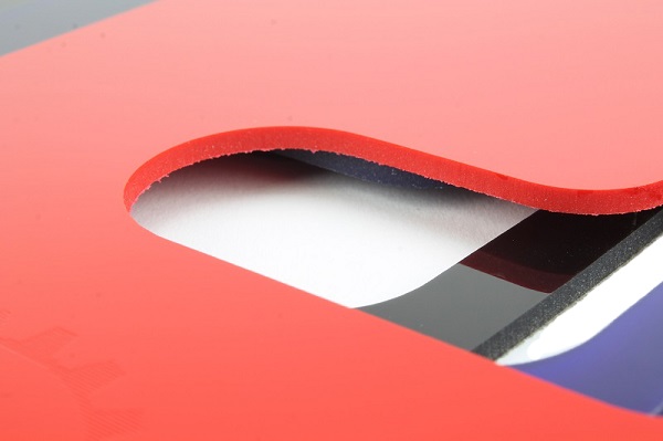
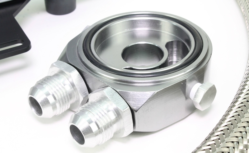
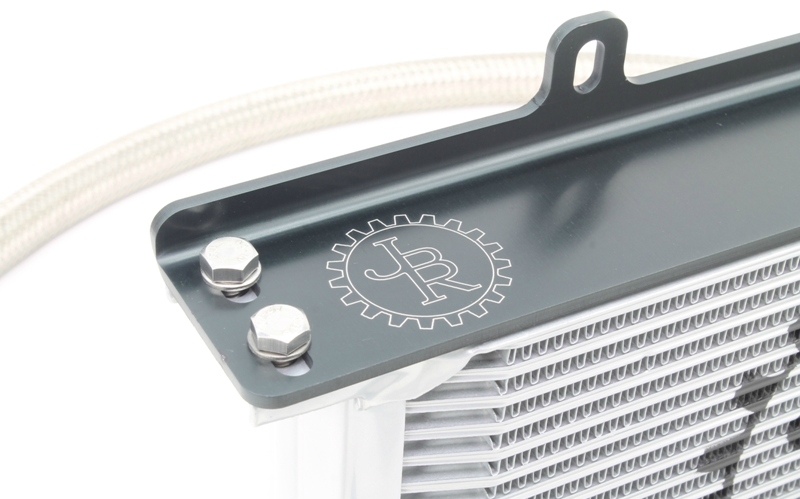
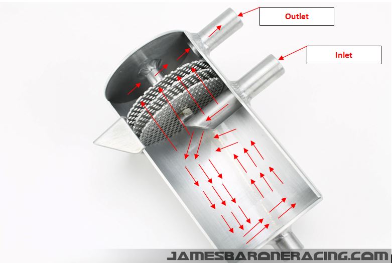
In this cut-away of the JBR oil catch can, you will see the inlet, the outlet and the baffling that separates them. The crankcase gas enters the catch can through the bottom port. Due to the size of the can, a pressure drop occurs as the gas enters allowing for oil to begin falling out of suspension. As the gas travels around and eventually up towards the outlet, it must pass through a series of three perforated baffles with hundreds of .063″ holes in each. Not only do the holes in the baffle plates greatly increase the amount surface area, a capillary action is also created. That, combined with surface tension, results in adhesive forces between the oil and holes in the baffles. The oil clings to the baffles and as it accumulates it drips off and is collected in the bottom of the can to be drained off at each oil change.

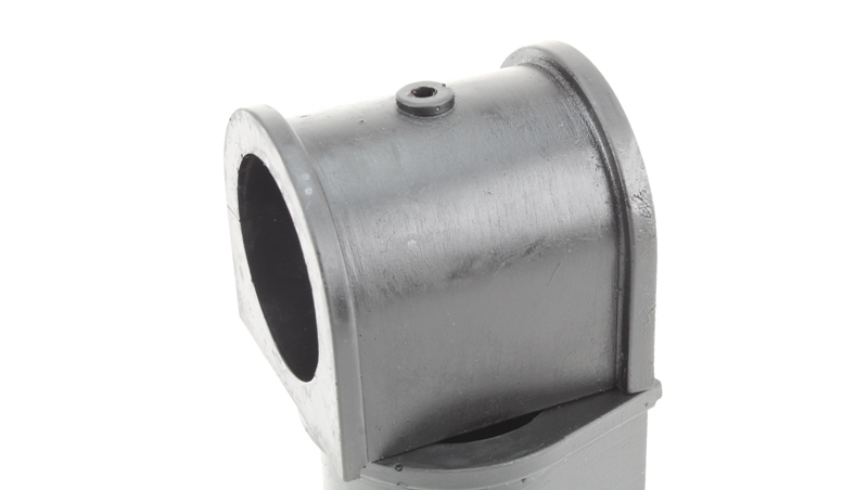
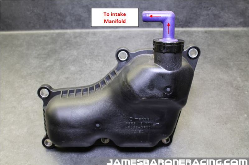
Well if this is such a problem why isn’t Mazda including one? Well, they are, sort of. It’s called an oil separator and it’s located on the side of the engine block behind the intake manifold.

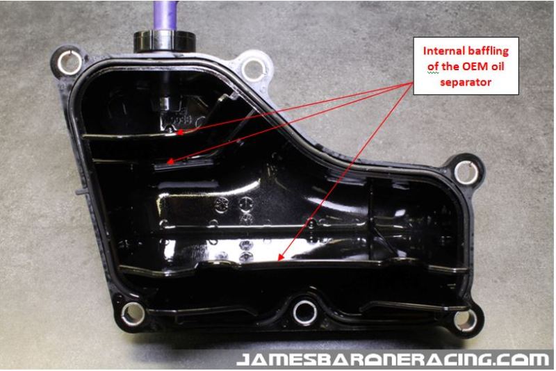
When we removed the oil separator from our 2016 Miata with the same 2.0L motor as our customer had, we found oil making its way past the baffling headed towards the outlet of the oil separator. It appears to work, just not very well.

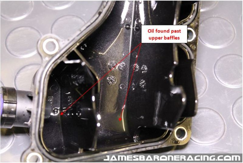
At the time we tore into our new Miata it only had 31 miles on it so everything was nice and clean. After seeing what we saw on the same motor with only 4463 miles, a catch can was going on immediately!

With just over 900 miles it’s time for us to change the oil in our Miata.

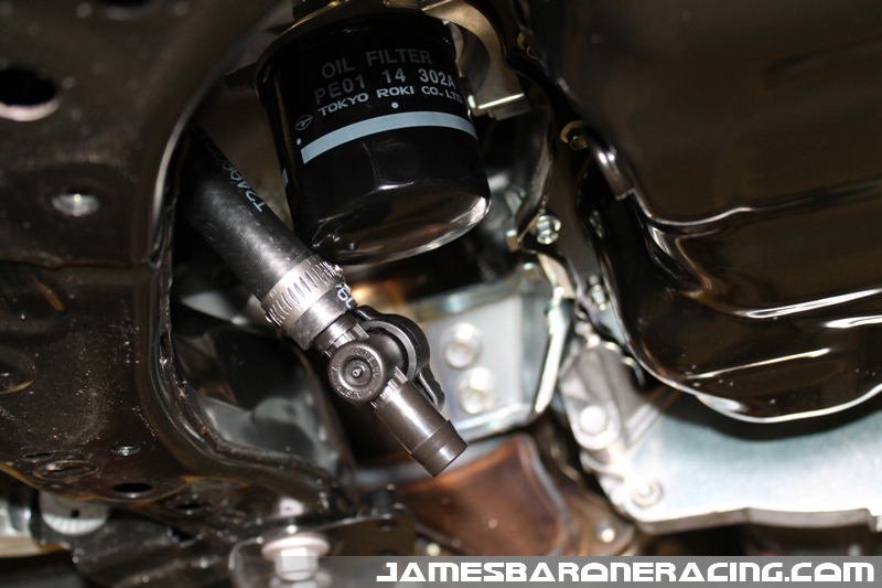
With the drain for the catch can located right by the filter housing, we can easily open the valve and empty its contents.

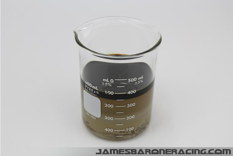
We were pleased to discover that we had accumulated a mixture of oil, water and fuel just shy of 50ml! Our catch can is doing its job well and our valves are being kept as clean as possible.

Below is a picture of the typical amount collected from our Mazdaspeed 3 at its regular 5k mile service interval. After it’s allowed to sit for a few days, there’s pretty clear separation of the oil, water and fuel that’s collected.

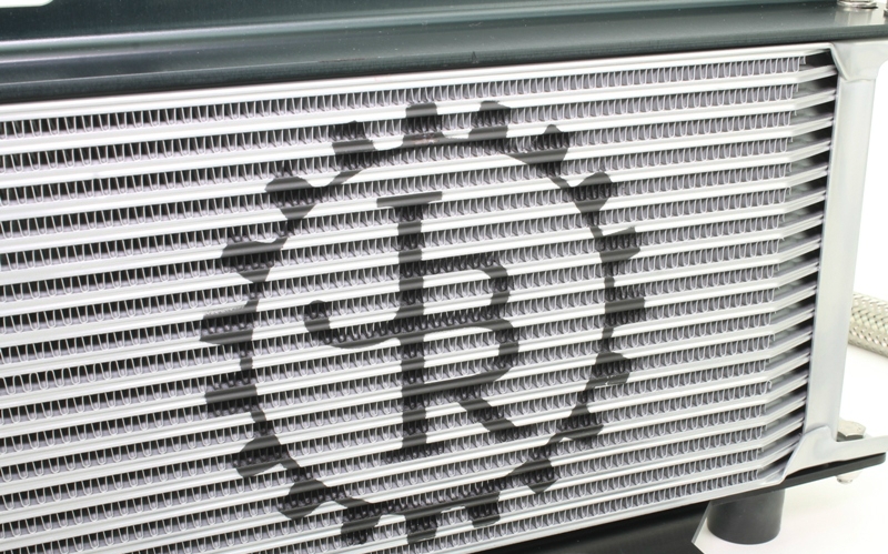
We’ve been making and testing Oil Catch Can Kits for most Mazda’s and  a few Ford vehicles for several years now. It’s our opinion that any engine utilizing direct injection fueling can only benefit from an oil catch can.

On a separate note…Many customers have asked if warranty claims can be denied for having a catch can installed? The answer is yes however, it’s highly unlikely and the burden of proof falls on the dealership to prove the catch can was the direct cause and ultimately the reason for the warranty claim in the first place. We’ve never heard of a warranty be denied for a vehicle having a catch can installed.

We’ll be sure to provide future updates on both our customer’s Mazda 3 and our Miata in the upcoming year to see how both are doing.


UTUBETwitter  Facebook Email